Automotive Resources
| Gauge Install |
 |
 |
 |
| Written by Administrator | ||||||||
| Monday, 25 April 2011 15:05 | ||||||||
|
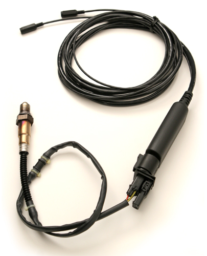
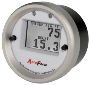
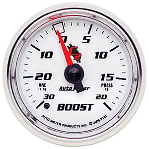
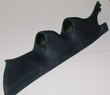
I was at the Mission drag strip quite often last year. I experimented with a few different tunes to get the most out of my 6.1. I decided that I needed to get a wide band O2 sensor in order to monitor my air fuel ratio. I ended up purchasing an Innovate LC-1 wide band O2 system. This unit came with an O2 sensor and a small ECU module. It has two analog outputs that correspond to the measured AFR reading. It also has a serial output for data logging. To display the AFR reading, I purchased an Aeroforce Interceptor. The is a 2" gauge that has two analog inputs and also connects to the car's ODBII interface which allows it to display any parameter available on the ODBII bus. To get ready for a possible future upgrade ;) I also installed a Autometer C2 mechanical boost gauge. To mount the gauge I purchased a Razor Edge A-Pillar pod. Razor edge take a factory A-Pillar panel, mount two 2" gauge pods, and cover the panel with black fabric. It is quite a nice looking unit but a real bitch to install gauges into. There is very little room to get your hands at the back of the gauges to install the thumb screws that hold the them in place. The mounting bracket that came with the boost gauge was way too big to fit in this pod so I had to make a custom bracket.
To power the LC-1 and Interceptor, I had to run a switched power source to the components. I purchased a Painless Cirkit boss. This device gives you three additional fused circuits to power accessories. It is potted so can be mounted in the engine bay. The CirKit boss requires a constant power feed as well as a switch power feed. The switched power is used to trigger a relay within the CirKit Boss to enable the three fused outputs. I mounted the unit next to the front power distribution module in the engine bay, bolted to the right finder well. Thanks to Speedy from SpeedysGarage.net, the connection to a switch power source was made through and existing unused fuse within the PDC. One of the connectors on the bottom of the PDC had a wire missing from one location (pin 10 of connector C6). I added my own pin/wire to fill this location and ran it to the CirKit Boss. This made for a very clean wiring solution. Its hard to tell that this additional component is not a stock item. I also mounted the LC-1 in the engine bay, this one under the brake master cylinder. This is close to the left exhaust manifold/cat which is where the new O2 sensor will be installed. I ran the LC-1 wiring harness and two of the CirKit Boss power feeds into the passenger compartment through a hole in the firewall. This is where I had previously routed the front camera cable. I also ran the boost gauge pressure line through this same hole. To install the interior components I remove the original pillar trim, upper cowl trim under the pillar, and the lower dash panel. This gave lots of room to run the mess of wires that had to be installed. The boost gauge back-light ended up being much to bright so I had to install a Autometer PWM dimmer. This dimmer runs off the dash illumination power which allows the back-light to be dimmed by a potentiometer on the dimmer control and still be further dimmable using the car's dash dimmer controls. All the wires were covered with corrugated conduit to tame to bundle of wires. After getting everything installed and working, I ran into a problem. I never tested the gauges with the car running, I jumpered the power and tested everything with the car off. Well, that was a mistake. I put all the interior back together only to find out that the Interceptor display could not be read while the engine was running. As soon as the engine started, the LCD contrast went south and could no longer be read. So, I had to rip the interior apart again :( I put a scope on the power to the Interceptor and there spikes present that were about 1V peak to peak. This did not seem too bad and I would expect the Interceptor to filter them out. I added a filter to the power supply to see if this would help and sure enough, the LCD came back to life. It seems that the Interceptor has a poor power input circuit. Just when I thought I had it licked I ran into another problem with the Interceptor. When the vehicle starts the gauge keep resetting just before it gets to the scan display. If I quickly turn the vehicle off and on it works fine again. I have heard others having problems with this when connected to a LC-1 so it looks like I may not be alone. I am still working through this issue and do not have a solution as yet. Update! May 8 2011 I think I found a solution for the Interceptor reset problem. I thought the problem may be that the analog output of the LC-1 is at state during the O2 sensor warm-up that is not compatible with the Interceptor. I remembered that there was an advanced menu in the LC-1 programming that allowed you to set a particular voltage during the warm-up period. I loaded the LC-1 programmer and set the output voltage to 2.5V during O2 sensor warm-up. So far this seems to have fixed the issue. The interceptor now boots and displays an AFR of 16.3 until the LC-1 activates and then show a AFR of 14.5 at idle. This definitely seem to be a bug in the Interceptor software. Not sure why they can not figure this out. Update. May 20 2011 Well, it looks like the reset problem is still occurring occasionally. I have now heard that there is a firmware update for the gauge that may solve this issue. I may have to bight the bullet and remove my pillar cover and send the gauge back for re-flashing. |
||||||||
| Last Updated on Sunday, 22 May 2011 10:15 |